Beginning Maker Techniques and Technology

A PCC Winter 2019 course for students of the Opening Doors Project.
Instructor: Jordan Laurent
Email: jordan.laurent@pcc.edu
Week 1: Jan 7-11
Week 2: Jan 14-18
Week 3: Jan 22-25
Week 4: Jan 28-Feb 1
Week 5: Feb 4-8
Week 7-8: Feb 18-Mar 1
Week 9-10: Mar 4-15
Week 9-10: March 4 - 15, 2019
For the next two weeks, we will be building and designing a digital clock using the DS3231 real-time clock (RTC) component and a 16x2 liquid crystal display (LCD), finishing it out with a custom laser cut or 3D printed enclosure.
Building an Arduino-powered Digital Clock
Step 1: Construct the circuit according to the image here.
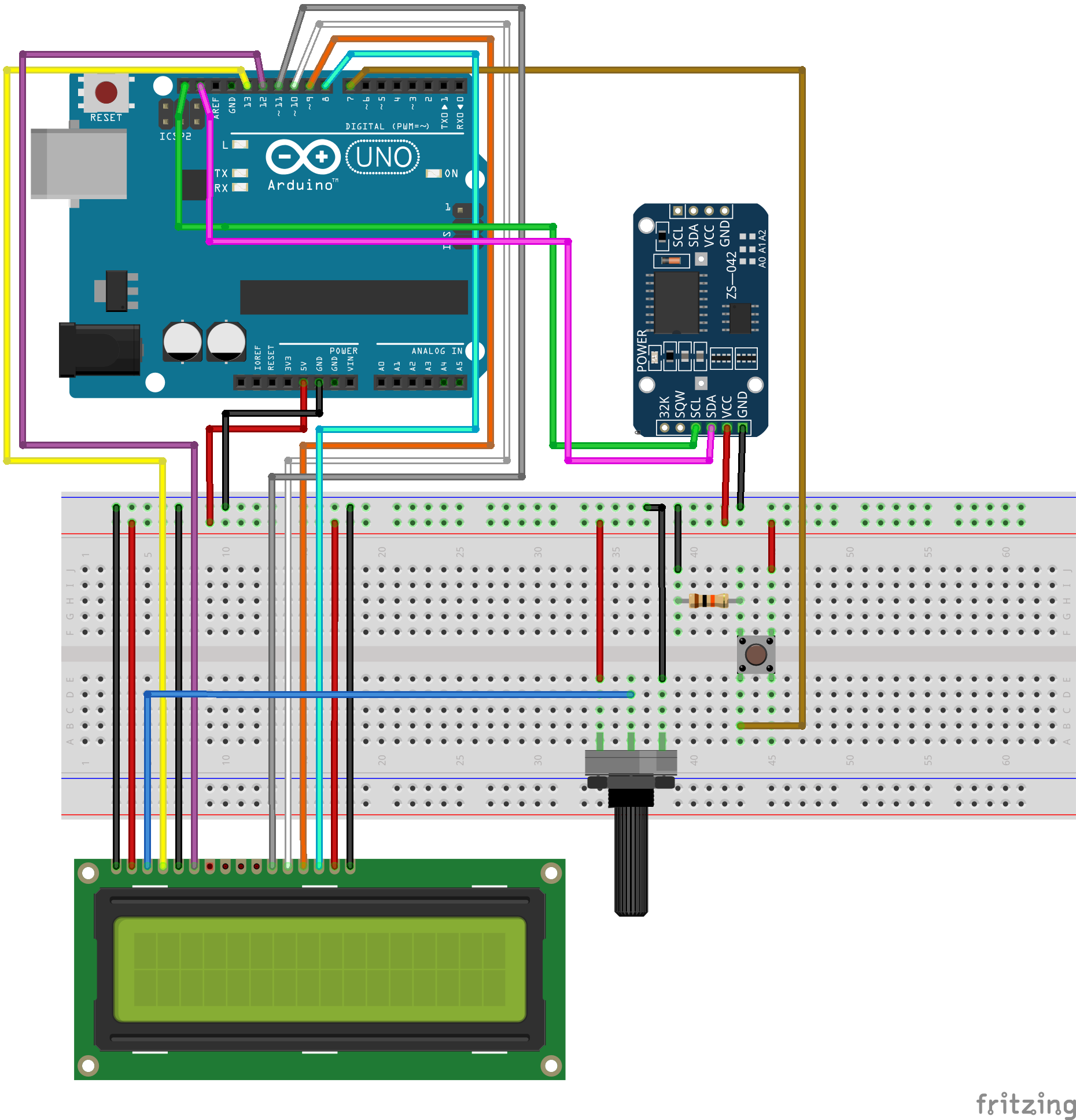
Step 2: Download the RTC DS3231 library from this website and save it to your Downloads folder. Connect the RTC to your Arduino and breadboard, then follow these steps to add your new DS3231 library to the Arduino IDE:
- Open the Arduino IDE
- In the toolbar at the top, navigate to “Sketch” -> “Include Library” -> “Add .ZIP Library”
- Find the DS3231.zip file you downloaded above, and click Open
- Your new library should now be imported into Arduino IDE
Step 3: Copy and paste the following code into a new Arduino file:
#include <DS3231.h>
#include <LiquidCrystal.h> // includes the LiquidCrystal Library

const int rs = 13;    // Set up pins for LCD screen
const int enable = 12;
const int d4 = 11;
const int d5 = 10;
const int d6 = 9;
const int d7 = 8;
const int button = 7; // Set pin for button
byte buttonState = 0;

DS3231 rtc(SDA, SCL);
LiquidCrystal lcd(rs, enable, d4, d5, d6, d7);

void setup()
{
  lcd.clear();      // Clear the LCD screen
  rtc.begin();      // Initialize the DS3231 RTC
  lcd.begin(16,2);  // Initialize the LCD screen and set the columns and rows

  pinMode(button, INPUT_PULLUP); // Initialize button as INPUT

//  rtc.setTime(22,53,30);  // Uncomment this line to reset the time
//  rtc.setDate(3,10,2019);  // Uncomment this line to reset the date
}

void loop()
{
  buttonState = digitalRead(button);
  if(buttonState == HIGH){   // If button is pressed
    lcd.clear();
    lcd.setCursor(0,0);   // Set the cursor at column 0, row 1
    lcd.print("Date: ");
    lcd.print(rtc.getDateStr());  // Prints the date
  } else {    // When the button is NOT pressed
    lcd.clear();
    lcd.setCursor(0,0);   // Set the cursor at column 0, row 0
    lcd.print("Time:  ");
    lcd.print(rtc.getTimeStr());  // Print the time
  }

  delay(1000);  // Delay for one second
}
Step 4: Read the comments in the Arduino file BEFORE uploading to set the time and date on your DS3231 Real-Time Clock. Note that by default, the LCD will display only the current time, while pressing the pushbutton will set it to display the date. Examine the code and think about what you might do display both at the same time.
Step 5: Choose an additional component. Consider what you will want to add to your clock - is it an alarm clock? Add a buzzer and a way to set the alarm. Does it display the current temperature and humidity? Use the DHT11 sensor. What if your clock lives in a potted plant that you never remember to water? A water level sensor might help you to keep an eye on that. You will have instructional support with code and wiring, so let the creative sparks fly.
Step 6: Begin laying out your box idea - sketch your proposed design for either the laser cutter or 3D printer. This prototype phase is important - there are a number of variables that can be hard to account for without prior experience, such as what components will be difficult to mount properly, which components should be accessible from outside the enclosure, and what your ideal material for the enclosure should be based on your environment. Once you have completed this step, we can begin to account for materials and methods of construction.
| ← Previous Week | Next Week → |